
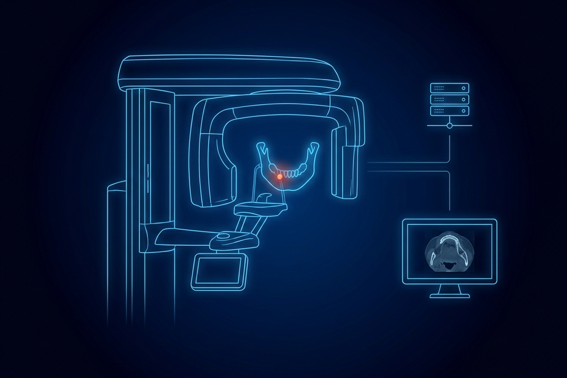
An intraoral CMOS sensor a few centimeters across carries a specified resolution of 25.6 line pairs per millimeter. A clinical flat-panel detector for general radiography commonly lands in the low single digits. Both write DICOM, and a viewer that tiles the intraoral image into a fixed thumbnail grid, the way it would tile a study of several hundred slices, has already thrown the difference away.
Resolution is one of four places a dental study diverges from a radiology one. How the image was acquired, how the teeth in it are numbered, and what the display is held to are the other three. A dental viewer answers all four differently, and getting them wrong does not stop the file from opening. The clinician just cannot read it the way the study demands.
What Counts as a Dental Image, and Why the FDA Labels Cut Differently
DICOM’s own documentation describes dental radiography as several distinct acquisition categories, not one. The informative annex added to the radiation dose reporting standard defines intra-oral radiography as imaging with “an X-Ray Detector placed within the patient’s mouth”, the source typically on a movable arm outside it. Cephalometry and panoramic dental radiography both use what the standard calls a panoramic X-ray system, but they are different studies. Cephalometry images the head for orthodontic treatment, typically in specialist orthodontic clinics; panoramic dental radiography images the head for dental treatment.
For an integrated panoramic system, the standard states plainly that “both the X-Ray Source and X-Ray Detector rotate around the patient’s head.” Cone beam CT is a fourth category again: a gantry with a rotating source and detector that reconstructs a volume rather than a single projection.
The FDA’s dental x-ray regulations do not cut along those same lines, which is worth knowing before anyone reads a regulatory label as a statement about image format. The agency divides on where the x-ray tube sits, not on how the image is acquired. 21 CFR 872.1810 covers an intraoral source system, and its identification paragraph is explicit: “The x-ray source (a tube) is located inside the mouth.”
Ordinary periapical and bitewing imaging does not work that way. The detector goes in the mouth and the tube stays outside it, which puts those systems under 21 CFR 872.1800, the extraoral source regulation: “The x-ray source (a tube) is located outside the mouth.” Panoramic and cephalometric units clear under that same regulation. Both regulations put their devices in Class II, and neither classification says anything about the pixel data a viewer will be handed.
Dental cone beam CT leaves the dental part of the code altogether, landing under 21 CFR 892.1750, the computed tomography x-ray system regulation. The FDA’s dental CBCT page states that classification directly. A viewer built to open one of these formats correctly is not automatically built to open the other three.
Intraoral Sensors and PSP Plates: High Resolution in a Small Frame
A general radiology viewer is built around volume. A chest or abdominal CT study can run to several hundred slices, and the viewer has to scroll and window across that many images without lag. A DICOM viewer built for that task is optimized for throughput across a large, deep study.
An intraoral periapical or bitewing image is closer to the opposite problem. The sensor’s active area is a few centimeters across. The entire diagnostic task sits inside that small frame: an early carious lesion, a hairline root fracture, the margin of a restoration.
That is why intraoral detectors are built for resolution rather than throughput. A peer-reviewed comparison of intraoral detectors in Imaging Science in Dentistry reports the specified figures for both: 25.6 lp/mm theoretical resolution for the CMOS sensor, 14.3 lp/mm for the photostimulable phosphor (PSP) plate. General radiography runs several times lower.
The federal digital chest radiography standard used for coal workers’ health screening sets a spatial resolution floor of 2.5 line pairs per millimeter. Clinical flat-panel detectors for general radiography commonly land in that same low single-digit range. A dental viewer that downsamples an intraoral image to fit a fixed thumbnail grid, the way a radiology viewer might tile a large study, throws away resolution the sensor was built to deliver.
Panoramic and Cephalometric Acquisitions Are Not a Single Projection
A standard projection radiograph, the kind a general radiology viewer is built to expect, comes from one fixed geometry: a source on one side, a detector on the other, a single exposure. Panoramic and cephalometric dental images are built differently. DICOM’s description of an integrated panoramic system states that the source and detector move together, rotating around the patient’s head over the course of the exposure. The result is a single flat image of a curved structure, the dental arch.
That acquisition method carries a consequence a viewer cannot skip. Magnification is not constant across a panoramic image the way it is across a chest film. A study in Imaging Science in Dentistry on panoramic measurement accuracy at different head positions found: “Significant differences were noted between the radiographic measurements and true values in different positions”. The focal trough itself “is narrow in the anterior and wider in the posterior areas”, the study noted, so a small positioning change distorts the front teeth more than the back ones.
A viewer that lets a clinician draw a linear measurement on a panoramic image without surfacing that variable magnification is handing back a number that looks precise and is not reliable. Cephalometric images share the acquisition method but serve a different task, orthodontic landmark analysis, which depends on consistent patient positioning and a calibration reference built into the image rather than on pixel spacing alone.
None of this shows up in the DICOM header the way slice thickness or pixel spacing does. It has to be handled in how the viewer presents its measurement tools, and whether it warns a clinician about what a panoramic measurement can and cannot support.
Cone Beam CT: a Volumetric Dataset Built for Small, Fine Detail
Cone beam CT is DICOM’s fourth dental acquisition category, and the one that looks most like general radiology on the surface. A rotating gantry acquires projection data and reconstructs it into cross-sectional images, the same basic principle behind a diagnostic CT scanner. What differs is scale.
CBCT voxels are isotropic, equal in all three dimensions, and a comparison of small-field CBCT units puts the range at 0.4 mm down to as small as 0.075 mm. One published implant-planning study reported scans acquired at a 0.15 mm voxel size across a 12 by 8 cm field of view. That scale is chosen to resolve fine anatomy, such as a root canal system, within a volume covering only part of the jaw.
A general CT scanner optimizes for a large field of view across an entire body region. Dental CBCT optimizes for detail inside a small one.
The reformatting a clinician wants differs too. Multi-planar reconstruction rebuilds axial, coronal, and sagittal planes from a volume. A dental CBCT reading task more often calls for a cross-sectional slice built perpendicular to the curve of the dental arch, the view implant planning depends on. It also calls for a panoramic-style reformat generated from the volume, instead of acquired directly.
A viewer that offers only the three standard radiology planes has not delivered what a dental CBCT study is actually read with.
Tooth Numbering and Mounting: What a Dental Viewer Has to Get Right
A radiology viewer orients a chest or abdominal image to a single, well-established convention and stops there. A dental viewer has to go one step further. It has to identify which specific tooth is in front of the clinician, correctly, every time, because the wrong tooth read as the right one is a patient-safety error, not a cosmetic one.
DICOM itself maintains dedicated coded terminology for this. Context group CID 4018, built specifically for intra-oral radiography, maps every permanent tooth to the international ISO 3950 (FDI) two-digit notation, quadrant first, tooth position second. That international standard is what DICOM’s own Digital Intra-Oral X-Ray Image IOD carries. The IOD extends the general Digital X-Ray Image IOD, layering on intra-oral-specific attributes like image laterality and positioner type.
United States clinical practice, though, mostly runs on a different scheme. The Universal Tooth Designation System is maintained by the American Dental Association and carried as its own code system in HL7 terminology. It numbers permanent teeth 1 through 32, starting at the upper right third molar and working around the arch.
A viewer serving a US dental practice has to display tooth references the way the clinician works, in Universal numbers, even where the underlying data or an international device defaults to FDI notation. Getting that mapping wrong, or leaving it to the clinician to translate in their head, is exactly the kind of gap that looks fine in a demo and causes a mistake in practice.
The physical convention behind all of this is older than DICOM. Film-based intraoral radiographs are mounted so the image is viewed as if looking at the patient’s face, a labial-mounting convention long recommended for consistency across a practice. A digital dental viewer has to reproduce that same orientation in software, by respecting the sensor’s own laterality and positioning data, or a left and right side can silently swap on screen.
Display Expectations That Diverge From Diagnostic Radiology
Diagnostic radiology reading displays are held to a specific, published bar. Interpretation displays are expected to reach at least 350 cd/m2 of luminance. They are also expected to be calibrated to DICOM’s Grayscale Standard Display Function, GSDF, with that calibration checked and recorded on an interval.
No dental equivalent appears to exist, and that claim rests on a single published source rather than a body of them. A peer-reviewed study of monitors used for dental radiographic interpretation found measurable, significant differences in diagnostic performance tied to monitor brand and to a monitor’s proximity to a window. Its authors wrote of AAPM TG18 and DICOM’s GSDF: “Unfortunately, not only are these standards not mandated worldwide, but they were developed for medical, not dental radiology.”
On their own market they claimed no more than they knew: “To the extent of the authors’ knowledge, in Australia there are no specifications for display monitors used for radiographic interpretation in dentistry.” Treat that as an absence nobody has documented closing, not as a standard that exists and is being ignored.
That gap does not mean display quality is irrelevant to a dental viewer. It means the question is a different one. A radiology reading display is qualified against a luminance and contrast regime because faint density differences carry the diagnosis.
A dental viewer’s display question is fine spatial detail and geometric accuracy instead. Can the screen and the rendering path preserve the resolution an intraoral sensor captured? Does a panoramic or CBCT measurement carry an honest account of its own magnification?
Five Things to Test Before Promising Dental
Before a partner claims dental support on top of any imaging platform, five behaviors are worth testing directly:
- Does the viewer render an intraoral image at the sensor’s native resolution, or does it downsample to a fixed display grid?
- Does it recognize panoramic and cephalometric acquisitions as their own geometry, with magnification handled explicitly rather than assumed?
- Can it reformat a CBCT volume along the dental arch, not only into the three standard radiology planes?
- Does it map tooth references to the numbering scheme the practice uses, Universal or FDI, rather than leaving that translation to the clinician?
- Does its orientation logic reproduce the standard viewed-as-facing-the-patient convention reliably, for every acquisition type it supports?
Supported, on its own, answers none of the five. Ask which study type the word covers, and which of the five behaviors comes with it.
All five sit above the transport layer rather than in it. DICOM Query/Retrieve, Storage, and the underlying archive services behind a general-purpose viewer, the kind EBM mAIn PACS® lists as native DICOM services, work the same way regardless of which modality is producing the study. Rendering fidelity, reformatting logic, coded terminology, and measurement honesty are what change. Build the evaluation checklist for a dental viewer around those, not around whatever a radiology viewer already happened to get right.